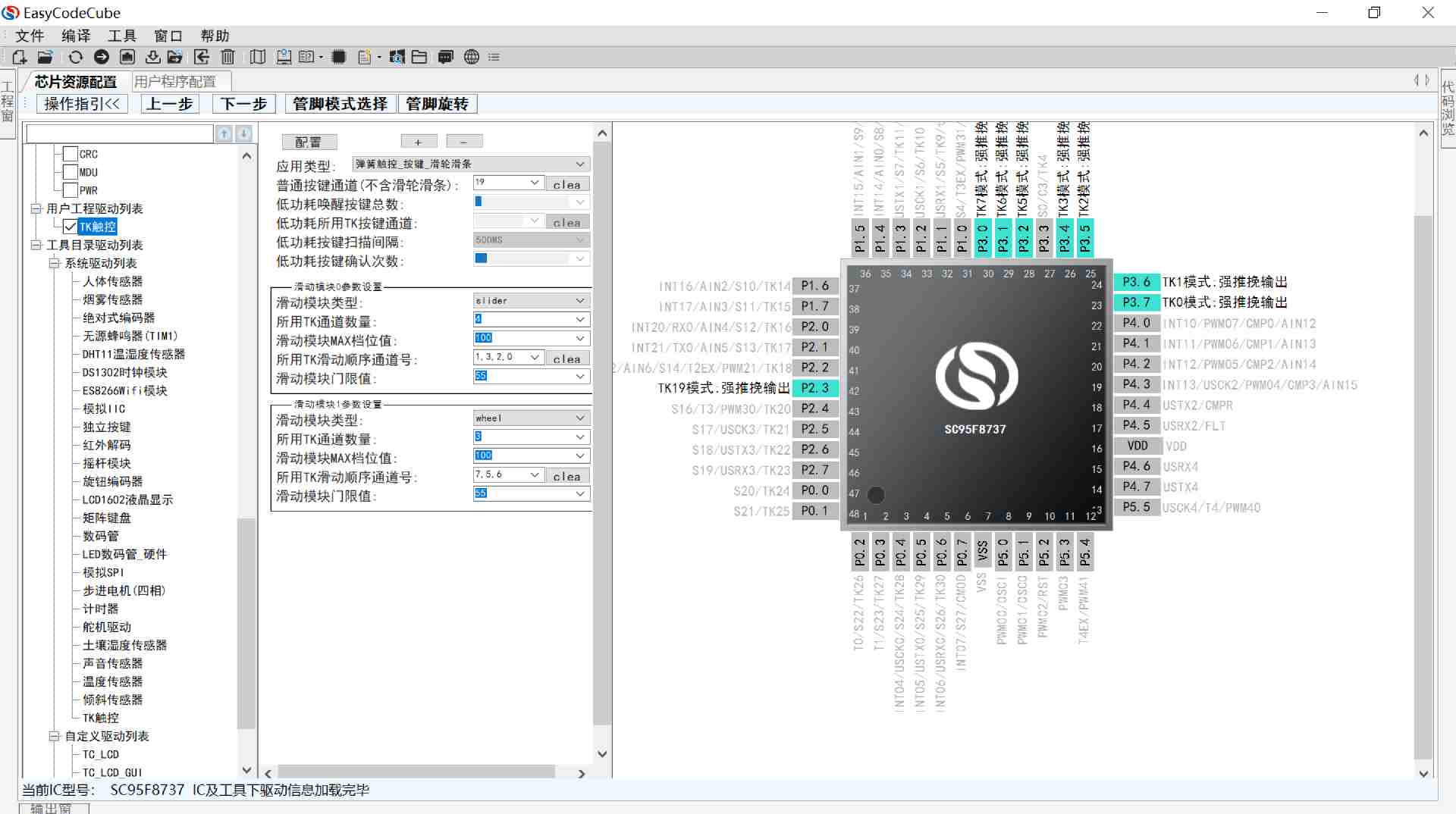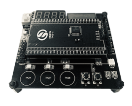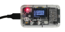
SC LINK PRO is designed for offline/online programming & simulation and TouchKey debugging of SC92F/93F/95F series MCU
Products
SC92F7596
Operating Conditions
l Voltage Range : 2.0V~5.5V
l Temperature Range : -40℃ ~ +105℃
EMS
l ESD
n HBM:MIL-STD-883J Class 3A
n MM:JEDEC EIA/JESD22-A115 Class C
l EFT
n EN61000-4-4 Level 4
CPU
l 8-bit 1T 8051 core CMOS microcontroller, instruction set fully compatible with MCS-51
Flash ROM
l 32 Kbytes Flash ROM
n The APROM area can be set to the range of IAP operation to 0K / 1K / 2K/all APROM through the Code Option setting item
l LDROM:
n Used to store the user's BootLoader boot code
n The LDROM can be set to 0K/1K/2K/4K through the Code Option setting item
l EEPROM:
n Independent 1K bytes EEPROM
n 100,000 times of writing, and more than 100 years of storage life at room temperature
SRAM:
n Internal 256 bytes
n 1792 Bytes Indirect Access RAM (XRAM)
n Additional 44 bytes PWM&LCD RAM
Unique ID:
l 96 bits Unique ID, which stores the unique identifier of an IC
System Clock(fSYS)
l Built-in high frequency 32MHz oscillator (fHRC)
l The system clock frequency (fsys) of the IC can be selected and set by the programmer as: 32/16/8/2.66 MHz @2.0~5.5V
l Frequency Error: Across (2.0~5.5V) and (-20 ~ 85℃) application environment, the frequency error is not more than ±2%
l The system clock can be automatically calibrated by 32.768kHz external crystal oscillator, after calibration HRC accuracy can be infinitely close to the accuracy of external 32.768kHz crystal oscillator.
Built-in low-frequency crystal oscillator circuit:
l 32.768k oscillator can be connected externally as a Base Timer clock source, and wake up STOP
Built-in low-frequency 32kHz oscillator (LRC):
l Used as the clock source for Base Timer and WDT, and wake up STOP
l Frequency Error: Across (4.0~5.5V) and (-20 ~ 85℃) application environment, after the register correction frequency error is not more than ±4%
Low-voltage Reset (LVR)
l 4 options of reset voltage: 4.3/3.7/ 2.9/1.9V
l The default value can be selected by the Code Option
Flash Programming and Emulation
l 2-wire JTAG programming and emulation interface
l Jtag-specific mode and regular mode can be set through Code Option
Interrupts (INT)
l Up to 12 interrupt sources including Timer0~Timer2, INT0~2, ADC, PWM, UART, SSI, Base Timer, CMP
l External interrupt contains 3 interrupt vectors, 16 interrupt ports. All can set up rising edge, falling edge, dual edge interrupt.
l Two-level interrupt priority capability
Digital Peripheral:
l Up to 42 bidirectional independently controllable I/O ports
n The pull-up resistors can be set independently
n All I/Os have large sink current drive capability (50mA)
n P0~P3L (P3.0/1/2/3) port source drive capability is divided into four levels
l Built-in WDT, optional clock frequency division ratio
l 3 standard 80C51 timers :Timer0, Timer1, and Timer2. Timer2 provides the Capture function
l 4-channel 12-bit PWM
l 1 independent UART communication port
l 1 UART/SPI/TWI communication interfaces (SSI)
l 1 integrated with 16 * 16-bit hardware Multiplier-Divide Unit (MDU)
LCD/LED driver:
n Choose one of two LCD/LED drive functions, share registers and I/O ports
n LED driver: 8 X 24, 6 X 26, 5 X 27, or 4X 28 segments
n LED segment port source drive capability is selectable in four levels
n LCD driver: 8 X 24, 6 X 26, 5 X 27, or 4X 28 segments
Analog Peripheral
l 17-channel 12-bit ±2 LSB ADC
n Built-in 1.024V, 2.4V and 2.048V reference voltages
n The ADC reference voltages is optional: VDD, 1.024V, 2.4V, 2.048V
n One internal channel can measure the voltage of the power supply
n The sampling clock of the ADC circuit follows the fSYS
n ADC conversion can be set to complete the interrupt
l 1 Analog Comparator
n The positive input of the analog comparator can be selected as:
u CMP0-3 One of four input ports
u Internal 1.5V reference voltage
n 4-channel input and 1-channel reference voltage input
n Can awaken the STOP mode
n 16-level optional comparison voltage
Power Saving Mode
l IDLE Mode: can be woken up by any interrupt
l STOP Mode: can be woken up by INT0~2, Base Timer, CMP.