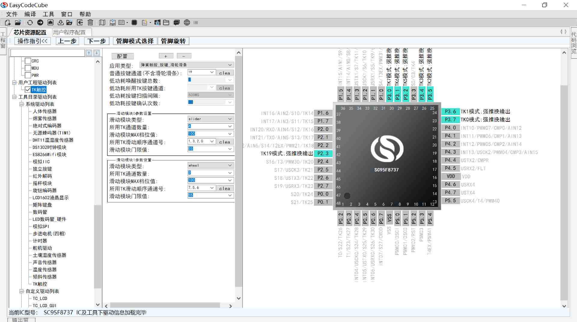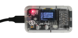
SC LINK PRO is designed for offline/online programming & simulation and TouchKey debugging of SC92F/93F/95F series MCU
Products
SC95F8612B
Operating Conditions
l Voltage Range: 2.0V~5.5V
l Temperature Range: -40℃ ~ +105℃
EMS
l ESD
n HBM:MIL-STD-883J Class 3A
n MM:JEDEC EIA/JESD22-A115 Class C
n CDM:ANSI/ESDA/JEDEC JS-002-2018 Class C3
l EFT
n EN61000-4-4 Level 4
Package
l 20 PIN: SOP20 / TSSOP20
CPU
l Super-high-speed 1T 8051 core
l The instruction set compatible with 8051
l The execution speed is about twice that of other 1T 8051
l Double data pointers (DPTRs)
l Flash ROM64 Kbytes Flash ROM
l MOVC disables addressing 0000H ~ 00FFH
l Can be rewritten 100,000 times
l APROM area allowed IAP operation in Flash can be set to 0K/1K/2K/All APROM by Code Option.
LDROM
l BootLoader code memory
l LDROM area can be set to 0K/1K/2K/4K by Code Option
EEPROM
l Independent 6 Kbytes EEPROM
l Can be rewritten 100,000 times, has more than 100-year preservation life in the ambient temperature of 25℃
SRAM
l 256 bytes on-chip direct access RAM
l 8 Kbytes on-chip Indirect access RAM
l 80 bytes PWM&LCD RAM
Flash Programming and Emulation
l 2-wire JTAG programming and emulation interface
System clock (fSYS)
l Built-in high frequency 32 MHz oscillator (fHRC)
n can be selected and set by the programmer as: 32/16/8/4 MHz@2.0~5.5V
n Frequency Error: Within ±1% @ -40 ~ 85℃ @ 2.0 ~ 5.5V
n Frequency Error: Within ±2% @ -40 ~ 105℃ @ 2.0 ~ 5.5V
n The system clock can be automatically calibrated by 32.768 kHz external crystal oscillator, after calibration HRC accuracy can be infinitely close to the accuracy of external 32.768 kHz crystal oscillator.
Built-in low-frequency crystal oscillator circuit:
l 32.768k oscillator can be connected externally as a Base Timer clock source.
Built-in low-frequency 32 kHz oscillator (LRC):
l used as the clock source for Base Timer and WDT and wake up STOP
l Frequency Error: After the register correction, within ±4% @ -20 ~ 85℃ @ 4.0 ~ 5.5V
Low-voltage Reset (LVR)
l 4 options of reset voltage: 4.3/3.7/ 2.9/1.9V,
l the default value can be selected by the Code Option
Interrupts (INT)
l Timer 0~Timer 4, INT0~2, ADC, PWM, UART, USCI0~5, Base Timer, TK, CMP 20 interrupt sources
l External interrupt contains 3 interrupt vectors, 16 interrupt ports. All can set up rising edge, falling edge, dual edge interrupt.
l Two-level interrupt priority capability
Digital Peripheral
l GPIO: Up to 18 bidirectional independently controllable I/O ports
n Independent setting of pull-up resistors
n P0~P3L(P3.0/1/2/3) port source drive capacity is controlled by four levels
n All IO ports have large sink current drive capability (50mA)
l Built-in WDT, optional clock frequency division ratio
l 5 Timers: Timer0~4、Timer1、Time2、Timer3 and Timer4
n Time2、Timer3 and Timer4 have Capture function
n Time2、Timer3 and Timer4 each can provide two conventional PWM
l 6-channel 16-bit conventional PWM
n Time2、Timer3 and Timer4 each can provide two conventional PWM
l 8-channel 16-bit multi-function PWM
n Public cycle and the duty cycle can be set separately
n Complementary PWM waveforms with dead zones can be output
l One independent UART communication port UART0
l Two UART/SPI/TWI communication interfaces (USCI)
n When USCI0 is set to SPI0, the driving capability of the pins corresponding to its signal port will be enhanced
l Built-in CRC check module
l Integrated with 16 * 16-bit hardware Multiplier-Divide Unit (MDU)
Analog Peripheral
l 17-channel high sensitivity TouchKey (TK) circuit.
n Applicable to TouchKey sensor, proximity induction and other TouchKey applications featuring high requirements on sensitivity
n Have very strong anti-interference ability which is able to pass 10V dynamic CS test
n Support self-capacitanceand reciprocal- capacitance mode.
n Support low power consumption mode.
n Complete development support: High-flexible touch software library, intelligent software of debugging.
l 9-channel 12-bit±2LSB ADC
n Build-in reference voltage of 2.048V, 1.024V and 2.4V
n The ADC reference voltages is optional: VDD, internal 2.048V, internal 1.024V and 2.4V
n 1 internal channel can measure the voltage of the power supply
n ADC conversion complete interruption can be set
l 1 Analog Comparator
n 4-channel input and 1-channel reference voltage input
n 16-level optional comparison voltage
Power Saving Mode
l IDLE Mode: can be woken up by any interrupt
l STOP Mode: can be woken up by INT0~2, Base Timer TK and CMP.